Electromagnetic Microphone Part One
Wed Jul 04 2018 07:00:00 GMT-0500 (Central Daylight Time)
Did you know that there is a wonderful world of annoying noise all around you?
What you hear in that video are oscillating electromagnetic fields. In some cases, like motor drive, they’re current pulses driving something at an audio frequency directly. Some noises are bursts of data happening so fast that the audible noise is caused by thousands of packets per second, each packet containing a large amount of it’s own ones and zeroes. A whole bus several wires wide might be a roaring waterfall of apparent stochastic noise, but the results are quite deterministic. Some of it, well, I have no idea. EMC is a whole industry with it’s own tricks and experts and ways-of-knowing.
What a mess! Government standards abound for reducing this noise to bearable levels, and it’s a good thing. Some of us remember losing TV reception when a nearby blender was making margaritas. If your aim is to sense this noise, for troubleshooting or for art, you can beat the system with the right sensor and enough amplification.
It’s worth knowing that the widgets you saw in the above video were a model of Elektrosluch made by the folks at LOM. They’ve been refining the design for that widget for at least four years and if you’d rather have something already built and proven then I’d suggest checking out their site. They’re a small batch manufacturer, and that takes a special kind of courage.
The Right Sensor #
So you want to listen to EM noise? You’re going to need an antenna. You want to do it at audio frequencies? You’re going to need an inductor.
Luckily, and rarely for electronics, the specs for our application are extremely loose. Our application is ‘wideband antenna’, and so we have very few requirements:
- Open shape to facilitate wide angle reception – bar core, drum core – avoid toroid, assembled transformer
- Ferrite material – high inductance per volume vs. laminated and powdered iron
- Enough Inductance to provide good signal – more than 1uH, aim for 25-100uH
This will get the job done, but there’s lots of room for improvement and experimentation.
This is a good chance to salvage some old junk. Bar and drum core inductors are both found in high current power supplies like those used in desktop computers. They’re used to suppress noise on the low voltage output rails, and because there are very high currents involved they tend to use beefy wire. You can get a good deal more inductance by removing the thick wire and wrapping them with thinner lacquered magnet wire. Any comfortable size wire to work with will do. You can disassemble the switching transformer and use what’s in there. Try to keep it between ten and one hundred turns. Getting crazy with hundreds of turns of guitar pickup wire would add a lot of capacitance, though I’m not sure even that would matter.
Similarly, you could poach the bar antenna from an old radio. You could try using it as is with the existing Litz wire, or remove the Litz (spool it up for later use?) and wrap magnet wire directly on the bar. Ferrite bar stock can be scored or notched with a file (even a nail file) and it will break somewhat cleanly. This would allow several small inductors to be made out of one bar.
High frequency transformers like the switching transformers in those computer power supplies use ferrite as well. careful disassembly of the core will reveal a pair of E shaped pieces of ferrite that can be used as is. The thinner parts can also be snapped off to provide a short bar of ferrite suitable as a core.
If you don’t have an electronics boneyard to pick through or you just want an easy solution then it’s the internet to the rescue. Any through hole (not surface mount) 100uH drum core inductor should work, current rating and dimensions are unimportant. They look like this. A quick trip to our favorite auction site with the keywords “100uH inductor” shows several places to get a ten pack of what we need for less than $5US shipped, though a closer seller may charge more.
That’s your antenna done. If you have your own source of amplification like a microphone preamp then you can wire up your antenna as per the following drawing:
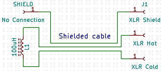
There’s no reference to ground required anywhere in the system, so this device is inherently balanced and can happily be wired directly to the differential inputs of a standard XLR or 1/4″ TRS jack. Don’t worry about trying to shield every last millimeter of the hot and cold wires, it’s not critical.
At first I thought there might be a danger of a phantom power system damaging itself on this, as the inductor presents a DC short across the + and – pins of the XLR. I’d forgotten that both pins are energized with phantom power and that the shield was the current return. This means that care must be taken with exposed connections at the inductor end of the cable if there is a chance of accidental activation of phantom power. If active it would cause 48VDC to show up on both pins of the inductor relative to the shield, which is often connected to a chassis or mains earth. A hand on the inductor and a hand on a metal case would make a circuit out of you. For safety’s sake it is critical to take care when experimenting, and if you’re satisfied that you have a working device then take care to heat shrink and insulate your connections properly. In the event that your amplifying device has no phantom power then you have nothing to worry about, though proper insulation is still recommended.
Finally, should you be lacking your own amplification, never fear. I’m working on a part two where I’ll make a simple circuit to bring the signal from our antenna up to line level.
Edit (2020AUG26): Part two was lost in the great cataclysm of 2020. I'll be rewriting it, but I've learned not to promise. Interested? Bother me with an email! Nothing motivates more quickly than knowing someone cares.